What is it?
Rapid Spanning Tree Protocol (RSTP: IEEE 802.1w) is a network protocol that is an advancement over Spanning Tree Protocol (STP: IEEE802.1D) that promotes high availability and “loop-free” topology within Ethernet networks.
A primary advantage to RSTP networks is that they offer high availability when compared to traditional daisy chain topology. When a network failure does occur, devices are able to continue communicating across the network as data can be rerouted around the failure. Critical systems depend on a high level of resiliency to faults and hardware failures and RSTP provides a key improvement over traditional network architectures by minimizing downtime.
RSTP prevents network loops when using multiple switches by blocking redundant paths on a network. In essence, the protocol is a set of rules by which switches on the network determine the most efficient way to send broadcasts across the network by establishing a “root bridge” and blocking specific ports with the purpose of preventing network loops.
Let’s look at why network loops are undesirable. There are three primary reasons why it is important to have a “loop free” Ethernet network, briefly explained here.
- Erratic MAC Address Tables
A MAC address table is what allows a switch to understand the topography of the network. It is the way a switch knows where traffic on the network is from and where it needs to be sent. If there is a loop on the network, the switch can receive an identical broadcast message from two different switches on the network. Every time a new copy of the broadcast message is received, the switch must update its MAC address table.
- Duplicate Data
When a switch receives a broadcast, but does not know the MAC address of the destination, it will send the broadcast out every port. This can create a situation where a device will receive duplicate copies of each broadcast being sent, wasting valuable bandwidth on redundant data. It can also lead to unrecoverable data errors.
- Broadcast Storms
Perhaps the most important reason to avoid loops in network topography is to prevent “broadcast storms.” A broadcast storm is created when switches in the network each send out multiple, duplicate copies of data (or “broadcast packets”) across the network. When switches are connected in a loop, data can travel to a switch from multiple paths. Because the MAC address table is unstable in a loop arrangement, a switch has no way to understand where data needs to be sent so it broadcasts the information out of every port. This data is received by all switches on the network, and rebroadcast out again because the recipient is still unknown. This can overwhelm switches and severely degrade network performance. The broadcast storm will continue until one of the switches fails or is disconnected from the system.
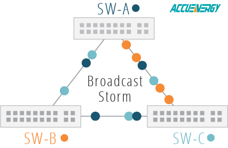
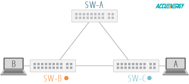
The following illustration shows three switches which are in a loop on the network. When one switch sends out a message, the two other switches on the network receive the message and forward the message to other switches on the network out of all other ports. For example, when Switch B sends a message to Switch A and Switch C, those switches receive the message and rebroadcast it to the other switches. When Switch A and Switch C initiate broadcasts across the network as well, the network can become congested with repeated broadcast messages, taking up bandwidth and slowing down the entire network.
Advantages of RSTP
RSTP, along with its predecessor STP, was developed for the purpose of preventing detrimental loops within a network.
RSTP prevents network loops by blocking redundant ports. A blocked port will still receive data, but will not send that data out to other devices on the network. This ensures that switches will receive only a single copy of a packet. If any of the active paths fail, one of the blocked ports will be used. The port that is selected depends on the topology of the configuration.
RSTP is an improvement over STP (Spanning Tree Protocol) mainly due to its reduction in convergence time – that is, the time it takes all switches on a network to reach a state of convergence, or agreement, on the topology of the network. In STP, there is substantial convergence time whenever there is a topology change or failure in the network, which typically lasts for 40-50 seconds. In a modern, high-demand networking environment, there is a constant need for increased speed and reliability and a delay of 40-50 seconds is generally unacceptable. RSTP reduces the convergence time significantly down to around 5-10 seconds.
Fortunately, many modern switches on the market automatically enable RSTP by default. Further, for networking environments with a mix of older and newer equipment, it is important to note that RSTP is backward compatible with the older STP standard.
How does RSTP work?
RSTP is a set of rules by which switches on the network determine the best way to route data on the network without redundancy. When it is enabled on a network, an algorithm determines the configuration of the spanning tree automatically.
The root bridge in the RSTP/STP is the bridge at the top of the spanning tree and is responsible for sending network topology information to other switches on the network. This is important for instances when there are hardware failures or other topology changes so that efficient, alternate paths are established with minimal delay.
STP vs RSTP Port States
RSTP can be described by three port states: Discarding, Learning, and Forwarding. The Disabled, Blocking, and Listening states described by STP have been combined into the Discarding state in RSTP. The functionality is similar.
In RSTP, the Alternate port and Backup port are allowed to directly enter the forwarding state which allows the convergence time of the network to be reduced significantly. In STP, the port must wait for the network to converge (40-50 seconds) before entering the forwarding state. This is a major advantage of RSTP over STP.
| STP | RSTP | Description |
| Disabled | Discarding | The port only listens for BDPUs. There is no forwarding, processing, or learning of MAC addresses. |
| Blocking |
| Listening |
| Learning | Learning | The port sends and receives BPDUs and also learns MAC addresses. Forwarding does not occur in this state. |
| Forwarding | Forwarding | The port can send and receive data, learn MAC addresses, and forward data to its destination. |
RSTP Port Roles
| Root Port | The port that receives Bridge Protocol Data Units (BPDUs) on the root bridge. These are messages that are exchanged between switches on the network. |
| Designated Port | The port selected in each local area network (LAN) segment which provides the lowest root path cost. The higher the link speed, the lower the cost value. |
| Alternate Port | If a port is not to be used as a designated port, it will become an alternate port. This is a backup for the root port in case of failure and is blocked during typical operation of the root port. |
| Backup Port | This is the backup for the designated port. If the root port fails, the backup port becomes the new designated port. The backup port is normally blocked with the designated port is operating correctly. |
The RSTP algorithm follows these general steps:
- Determine the root bridge: The switch with the lowest bridge priority will be the root bridge. If there is a tie, the switch with the lowest MAC address is selected.
- All interfaces on the root bridge are placed in a Forwarding state: In a forwarding state, the port will send and receive data and learn MAC addresses on the network.
- All other switches on the network (non-root) select a root port: The root port is the best path to the root bridge based on its port cost. The lower the port speed, the higher the cost. Therefore, the fastest port is chosen as the root port based on its low port cost. There is only one root port per non-root switch.
- Designated ports are selected: These ports are permitted to forward traffic and are also selected based on port cost. All root bridge ports are designated ports.
- All other ports are in a discarding (blocking) state: These ports are not passing data to other switches on the network and not updating MAC address tables.

Network configuration is outside the scope of this document. To determine whether your network has RSTP or STP enabled, contact your system administrator or consult your network hardware documentation.
RSTP in the AXM-WEB2
The AXM-WEB2 is an Ethernet communications module for the Acuvim II Series Meters which supports RSTP. This allows users to daisy chain multiple WEB2 modules together. There can be a maximum of 32 modules daisy chained together via Ethernet. RSTP can be enabled from the module’s web interface under the Network tab in the Communication Settings page. When RSTP is enabled in the module, an Ethernet bridge is created between Ethernet ports 1 and 2.
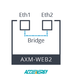
When this bridge is created, it allows the Ethernet ports 1 and 2 to send and receive data.
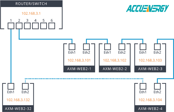
Connecting each module in an Ethernet daisy chain allows each of the modules to act as a network switch. Each module in the daisy chain will need to have its own unique IP address. The following image shows a 32 meter/module network with an Ethernet daisy chain.
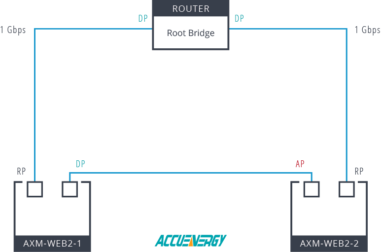
For a simple example of how RSTP works with the AXM-WEB2, we will use two modules. The example network diagram below shows an Ethernet network consisting of one router and two AXM-WEB2 modules.
- Let’s suppose the Router has the lowest MAC address in the network, it will then become the root bridge.
- The ports on the Router will then become the Designated Ports (DP).
- The Root Port (RP) is considered the best path to the Root Bridge (Router). From the diagram, the best paths are the “AXM-WEB2-1” and the “AXM-WEB2-2”.
- Both module connections have the same link speed of 1Gbps and they will have the same root path cost.
- Next, for “AXM-WEB2-1” and “AXM-WEB2-2,” we will need to know which one has the lower MAC address to determine which port roles are assigned.
- For this example, “AXM-WEB2-1” will have the lower MAC address; its ports become Designated Ports (DP).
- “AXM-WEB2-2” ports will then become the Alternate Port (AP) since it has the higher MAC address.
Enabling RSTP results in increased network speed and reliability without hardware upgrades or changing network architecture. It is a simple, cost-effective way to maximize efficiency on existing networks. Users with the AXM-WEB2 module with firmware 1.08 and above can take advantage of the RSTP feature.
 X
X 
 X
X  X
X  X
X