To get to the DO parameter settings screen:
- Press "P" and "E" simultaneously while in the general settings mode. Press "P" and "E" simultaneously to exit the DO parameter settings.
Note: This is only applicable to the Acuvim BL meter and Acuvim DL and EL meters with extended I/O modules.
In the DO parameter settings mode, you can press V/A to move to the next setting screen. If you will like to change these settings:
- Press "H" to switch the flashing digit in certain cases.
- Press "P" or "E" to increase or decrease a number.
- Press "V/A" to confirm the change and move to the next screen.
Note: There are two additional screens that are displayed on the Acuvim DL and EL meters; these are the Baud rate and parity screens. Since the Acuvim DL and EL have the option of an extended I/O module with a RS485 port, there is a baud rate and parity setting for this second RS485 port. Acuvim BL does not have these two screens.
The 1st screen "BPS" is the baud rate screen for the second RS485 port.
The 2nd screen "PARIT" is the parity for the second RS485 port.
The 3rd screen "d01 Mode" is the DO1 output mode setting. This is to select DO1 either as a pulse output or alarm output. 0 means pulse output while 1 means alarm output.
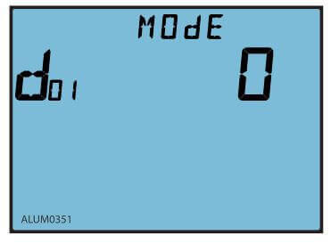
Figure 2: Setting the Digital Output Mode
The 4th screen "d02 Mode" is the DO2 output mode setting. This is to select DO2 either as a pulse output or alarm output. 0 means pulse output while 1 means alarm output.
The 5th screen "do CONST" is the DO pulse constant setting. This indicates the relationship between the energy value (kWh or Kvarh) and the pulse. This setting applies if DO is set as a pulse output.
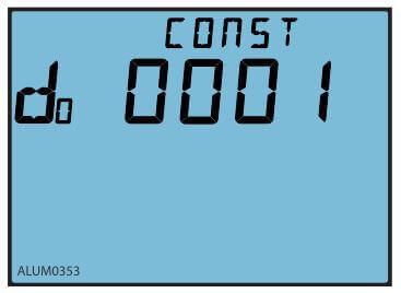
Figure 3: Setting the Digital Output Pulse Constant
To calculate what value to enter as the DO pulse constant setting, you will need to follow one of the procedures below. There is a procedure for meters with firmware below 2.01 and meters with firmware above 2.01
Procedure for meters with firmware 2.01 or newer.
First you will need to figure out how many pulses you want to represent 1 KWh or how many KWh will represent 1 pulse. The former is focused on smaller consumption.
In this procedure, we will assume 1 pulse = 10kWh is what is needed. Then follow these steps:
- Multiply the PT ratio and CT ratio i.e. (PT1/PT2) * (CT1/CT2) Example: PT ratio: 6600V/120V, CT ratio: 2000:5A => (6600/120) * (2000/5) = 22,000 Note: If no PTs were used, enter the PT ratio as the default on the meter, i.e. 400/400. If the CT2: 333mV, consider this as 1A for the calculation
- Divide 10KWh by 22,000 i.e. (10/22000) kWh = (1/2200) kWh
- This means 1 pulse = (1/2200) kWh; therefore 2200 pulses = 1 kWh
- Since we get 1 kWh = 2200 pulses, enter 2200 as the pulse constant the meter
Procedure for meters with firmware 2.01 or older
First you need to figure out how many pulses you need to represent 1 KWh or how many KWh will represent 1 pulse. The former is focused on smaller consumption.
You will need to enter the pulse constant based on the unit. The unit of the pulse constant is 0.1kWh (or kvarh).
If you want 1 pulse to represent 100kWh, this is equivalent to 1 pulse = 1000*0.1kWh. Therefore 1000 is the number you will enter into the meter.
The 6th screen "do WIDTH" is the DO pulse width setting. The DO pulse width can be set from 1 to 50. Each unit represents 20ms. For example if you set the number as 5, this represents 100ms (5 x 20ms). This setting applies if DO is set as a pulse output.
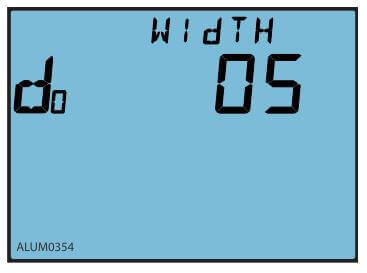
Figure 4: Setting the Digital Output Pulse Width
The 7th screen "d01 SEL" is the DO1 output item setting. You can select DO1 to output different types of energy. 0 means no output, 1 means import energy (Ep imp), 2 means export energy (Ep exp), 3 means import reactive energy (Eq imp) and 4 means export reactive energy (Eq exp). This setting applies if DO is set as a pulse output.
| Item Value | 0 | 1 | 2 | 3 | 4 |
| Energy Select | No output | Ep_imp | Ep_exp | Eq_imp | Eq_exp |
The 8th screen "d02 SEL" is the DO2 output item setting. You can select DO2 to output different types of energy. 0 means no output, 1 means import energy (Ep imp), 2 means export energy (Ep exp), 3 means import reactive energy (Eq imp) and 4 means export reactive energy (Eq exp). This setting applies if DO is set as a pulse output.
The 9th screen "do TIME" is the DO delay time for the alarm setting. This indicates how long the alarm condition will last before an alarm signal is triggered. It can be set from 0 to 255, and each unit stands for 300ms. For example if you set it as 20, this means 20*300ms = 6000ms.
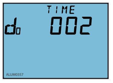
Figure 5: Digital Output Delay Setting
The 10th screen "do1 PARA" is the DO1 alarm output channel setting. This indicates what parameters you will like to monitor for the alarm conditions. Choose the parameter based on the numbers in the table below.
| Var | 0 | 1 | 2 | 3 | 4 | 5 | 6 | 7 | 8 |
| Item | Hz | V1 | V2 | V3 | V12 | V23 | V31 | I1 | I2 |
| Var | 9 | 10 | 11 | 12 | 13 | 14 | 15 | 16 | 17 |
| Item | I3 | In | P1 | P2 | P3 | Psum | Q1 | Q2 | Q3 |
| Var | 18 | 19 | 20 | 21 | 22 | 23 | 24 | 25 | 26 |
| Item | Qsum | Ssum | PF1 | PF2 | PF3 | PFsum | U_unbl | I_unbl | Dmd_P |
| Var | 27 | 28 | 29 | 30 | 31 | 32 | 33 | 34 | |
| Item | Dmd_Q | Dmd_I1 | Dmd_I2 | Dmd_I3 | S1 | S2 | S3 | Dmd_S | |
The 11th screen "do1 SIGN" is the DO1 inequality sign setting. This is to set what type of alarm condition you will like i.e. either greater than or less than. 0 means less than (<) and 1 means greater than (>).
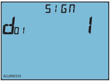
Figure 6: Digital Output Condition Setting
The 12th screen "do1 LIMIT" is the DO1 alarm limit setting. This is the alarm condition value for the parameter. The table below should be used to calculate the value that should be entered in the meter.
| Parameter | Relationship | Unit |
| Voltage V1, V2, V3, V12, V23, V31 | U=Rx x (PT1 / PT2) /10 | Volt(V) |
| Current I1, I2, I3, In | I=RX x(CT1 / CT2) /1000 | Amp(A) |
| Power Pa, Pb, Pc, Psum | P=Rx x (PT1 / PT2) x (CT1 / CT2) | Watt(W) |
| Reactive Power Qa, Qb, Qc, Qsum | Q=Rx x (PT1 / PT2) x (CT1 / CT2) | var |
| Apparent Power Sa, Sb, Sc, Ssum | S=Rx x (PT1 / PT2) x (CT1 / CT2) | VA |
| Power Factor PFa, PFb, PFc, PFsum | PF=Rx / 1000 | NA |
| Frequency | F=Rx / 100 | Hz |
| Load Nature (R/L/C) | 76/67/82 | NA |
| Voltage or current unbalance factor U_unbl, I_unbl | Unbl = (Rx/1000) x 100% | NA |
Here is an example to illustrate: If you want an alarm to be triggered when phase B current goes above 180A. In this example, we assume that the CT ratio is 200:
Rx is the value you need to enter on the meter.
From the table above: I = the actual current = 180A 180 = Rx * (200/5)/1000 Rx = 4500; therefore you should enter 4500 on the meter.
The 13th screen "do2 PARA" is the DO2 alarm output channel setting. This is the same as DO1 above.
The 14th screen "do2 SIGN" is the DO2 inequality sign setting. This is the same as DO1 above.
The 15th screen "do2 LIMIT" is the DO2 alarm limit setting. This is the same as DO1 above.
The 16th screen "bL ALARM" is the backlight blinking setting. This is to enable or disable backlight flashing during an alarm. 1 is to enable while 0 is to disable.
The 17th screen "PROFI" is the profibus address setting. This can be set from 0 to 126. This is only available when a profibus module is attached on the Acuvim DL or EL.
 X
X