Product Support
Acuvim II Analog Output Settings
Note: The Analog Output can only be activated through the display of the meter, to configure the range of the output you must use the AcuView software. Otherwise the meter will use the default input range.
Activating Analog Output

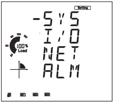
Figure 1: Parameter Selection Mode
- The cursor will be on 'SYS'. Press 'P' on this screen to move the cursor to the 'I/O' settings. Press 'V/A' to enter.
In the I/O parameter mode, you can choose the available modules attached to the meter. To do this, you can press:
- 'H' to return to the parameter selection mode
- 'P' to move the cursor downward and 'E' to move the cursor upward
- ‘V/A’ to select the module; this will enter the setting page for the I/O module that was selected.

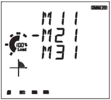
Figure 2: Analog Selection Page
Note: M11 represents AXM-IO1-1 while M31 represents AXM-IO3-1. For IO2 module select 'M21'
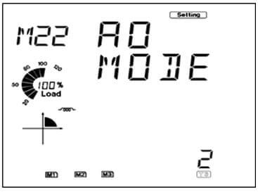
- Press 'P' to get to the 'AO MODE' screen.
Set the AO Mode according to the module option. That is, you can only set the AO mode as 0-20mA or 4-20mA if you have the 'Current mA' AO option. If you have the 'Voltage V' AO option, then you can set the AO mode as 0-5V or 1-5V.

Figure 3: Module Selection Page
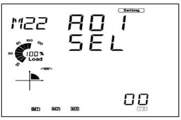
- Press 'P' to move to the 'AO1 SEL' screen.
- Select the parameter you will like to output through the AO1 channel.
- Press 'P' to move to the 'AO2 SEL' screen.
- Select the parameter you will like to output through the AO2 channel.

Figure 4: AO Selection Setting
| Setting Value | Transducer Parameter | Setting Value | Transducer Parameter | Setting Value | Transducer Parameter |
|---|---|---|---|---|---|
| 0 | Frequency | 1 | Va | 2 | Vb |
| 3 | Vc | 4 | Average Phase Voltage | 5 | Vab |
| 6 | Vbc | 7 | Vca | 8 | Average Line Voltage |
| 9 | Phase A Current | 10 | Phase B Current | 11 | Phase C Current |
| 12 | Average Current | 13 | Neutral Current | 14 | Phase A Real Power |
| 15 | Phase B Real Power | 16 | Phase C Real Power | 17 | Total Real Power |
| 18 | Phase A Reactive Power | 19 | Phase B Reactive Power | 20 | Phase C Reactive Power |
| 21 | Total Reactive Power | 22 | Phase A Apparent Power | 23 | Phase B Apparent Power |
| 24 | Total Apparent Power | 25 | Total Apparent Power | 26 | Phase A PF |
| 27 | Phase B PF | 28 | Phase C PF | 29 | Total PF |
| Parameter | Default Input Range |
|---|---|
| Frequency | 45 - 65 Hz |
| Volts An, Bn, Cn, Ln average | 0 - 480 V |
| Volts AB, BC, AC LL average | 0 - 831 V |
| Pwr Factor A, B, C, Total | -1 - 1 |
When using any of the three phase currents as the parameter to output, the following maximum value for that parameter is determined by the CT1 and CT2 settings.
Note: For meters with RCT, 333mV and mA current input take CT2 as 1.| Current Input of Meter (CT2) | Default Input Range |
|---|---|
| 5A | 0- (CT1*10)/CT2 A |
| 1A | 0- (CT1*10)/CT2 A |
| 333mV | 0- CT1/(CT2*10) A |
| RCT | 0- CT1/(CT2*10) A |
| 80/100/200mA | 0- CT1/(CT2*10) A |
| Power Parameter | Default Input Range |
|---|---|
| Watt A, B, C (kW) | -(V*I) -(V*I) |
| Watt Total (kW) | -3(V*I) - (3*(V*I)) |
| VAR A, B, C (kW) | -(V*I) - (V*I) |
| VAR Total (kW) | -3(V*I) - (3*(V*I)) |
| VA A, B, C (kW) | 0- (V*I) |
| VA Total (kW) | 0- 3*(V*I) |
