You can change the different I/O settings from this section; I/O such as Digital Input (DI), Digital Output (DO), Relay Output (RO), Analog Input (AI) and Analog Output (AO).
In the I/O parameter mode, you can choose the available modules attached to the meter. To do this, you can press:
- "H" to return to the parameter selection mode
- "P" to move the cursor downward and E to move the cursor upward
- "V/A" to select the module; this will enter the setting page for the I/O module that was selected
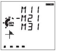
Figure 8: Module Selection Page
Note: M11 represents AXM-IO1-1 while M31 represents AXM-IO3-1.
In the I/O setting page for the module you selected, you can change the I/O setting of interest:
- Press "H" to return to the I/O module selection mode
- Press "P" to go to the next screen and "E" to go to the previous screen
- Press "V/A" to modify the setting. When in the settings modification mode, the setting parameter begins to flash:
- Press "H" to move the flashing cursor to the next position
- Press "P" to increase the number and "E" to decrease the number
- Press "V/A" to confirm the changes
AXM-IO1 (M11 or M12)
Digital Input (DI):
Digital Input (DI) can be used for pulse counting or for switch status monitoring:
- Setting the pulse counter enable screen to "0" means DI will be used for status monitoring while setting it to "1" means it will be used for pulse counting.
- On the pulse counter enable "IO CNTR ENBL" screen: 000001 means DI6 to DI2 are status monitors while DI1 is a pulse counter.
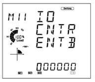
Figure 9: DI Mode Configuration
- On the Pulse Constant "IO CNTR CONT" screen: If DI is a pulse counter, set the pulse constant on this screen. When the number of pulses counted by the DI equals to the pulse constant, the pulse counter number will increase by one.
Relay Output (RO):
Relay Output (RO) can be used as a control output or alarm output.
On the Relay Output mode ’RO MODE’ Screen:
- Select the output mode for your relay output i.e. either control "CTRL" or alarm output "ALM".
Note: Control output is to manually switch on the relay, while alarm output is to trigger the relay output through an alarm event.
On the "RO OUT" Screen:
- When the Relay is set as a control output, you can choose between two control methods i.e. Latch mode "LATCH" or Pulse mode "PUL".
Note: Latch mode is to manually turn on and off the relay, while Pulse mode is used to turn on the relay for a set number of seconds before it goes back off.
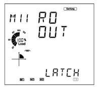
Figure 10: RO Mode Configuration
On the Relay Output Pulse Width "RO PUL WIDH" screen:
- If the Pulse mode is selected as the relay control method, then the Pulse width would have to be set. This is the time the relay will stay on after it has been manually triggered. The range is 50-3000ms.
AXM-IO2 (M21 or M22)
Digital Input (DI)
Digital Input (DI) can be used for pulse counting or for switch status monitoring:
- Setting the pulse counter enable screen to "0" means DI will be used for status monitoring while setting it to "1" means it will be used for pulse counting.
- On the pulse counter enable "IO CNTR ENBL" screen: 0001 means DI4 to DI2 are status monitors while DI1 is a pulse counter.
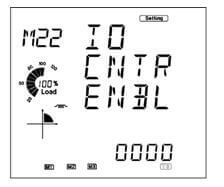
Figure 11: IO2 DI Mode Configuration
- On the Pulse Constant "IO CNTR CONT" screen: If DI is a pulse counter, set the pulse constant on this screen. When the number of pulses counted by the DI equals to the pulse constant, the pulse counter number will increase by one.
Digital Output (DO)
Digital Output (DO) can be used either as an alarm output or as an energy pulse output.
On the "DO MODE" screen:
- Select "PUL" for the digital output to send out energy pulses or select "ALM" for the digital output to send out digital signals during an alarm event.
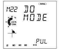
Figure 12: DO Mode Configuration
On the DO pulse width "DO PUL WIDH" Screen:
- Put in the pulse width for the digital output if DO is used as an energy pulse output. The range is 20-1000ms.
On the "DO PUL 1" Screen:
- Select the output energy type for DO1. Range from 0-4. I.e. Import active energy, export active energy etc.
On the "DO PUL 2" Screen:
- Select the output energy type for DO2. Range from 0-4. I.e. Import active energy, export active energy etc.
0: Represents No Output, 1: Represents Import active energy, 2: Represents export active energy, 3: Represents import reactive energy and 4 Represents export reactive energy.
You will also need to set the DO Energy Pulse Constant. This can be set in the
System Setting "SYS" screen. On the SYS page:
- Go to "S10 PUL CONT P" and set the pulse constant (Pulse/kWh) based on the calculation below
- Go to "S11 PUL CONT Q" and set the pulse constant (Pulse/kvarh) based on the calculation below
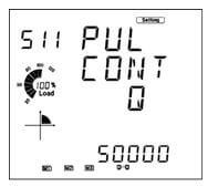
Figure 13: Pulse Constant Setting
Here is the procedure to calculate what value to enter on the meter for the DO Pulse constant. There are two procedures, one for all Acuvim II series meters and the other for Acuvim II model with firmware below 3.01
 X
X