First you need to figure out how many pulses you need to represent 1 KWh or how many KWh will represent 1 pulse. The former is focused on smaller consumption.
You will need to enter the pulse constant based on the unit. The unit of the pulse constant on the meter is 0.1kWh/pulse.
Therefore, if you need 1 pulse to represent 100kWh i.e. 100kWh/pulse; this is equivalent to: 1000*0.1kWh/pulse. 1000 is the number you will enter as the pulse constant into the software.
Analog Output (AO):
Under the ‘Raw Channel of AO’ section:
- Choose the AO 1 and AO 2 parameters
- Choose the ‘AO Type’ according to the module option. That is, you can only set the AO mode as 0-20mA or 4-20mA if you have the ‘Current mA’ AO option.
- If you have the ‘Voltage V’ AO option, you can set the AO mode as 0-5V or 1-5V.
Under the ‘AO Input/Output Transfer Curve’ section (Available only for meters with firmware 3.01 and above):
- Choose the type of slope for AO 1 and AO 2. I.e. Single Slope, Dual Slope or Triple Slope.
- Type in the Input Range based on the AO1 and AO2 parameters selected
- Type in the Output Range based on the module’s analog output option.
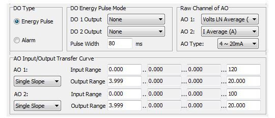
Figure 4: AXM-IO2 Settings
Note: Review the "Analog Output Relationship with Electrical Quantities" section of the user manual for more information and the relationship between the analog output and parameter ranges.
AXM-IO31/AXM-IO32
Digital Input (DI)
Digital Input (DI) can be used for pulse counting or switch status monitoring. Choose the DI type (state or counter) for all 4 DI’s.
- If DI is a pulse counter, type in the pulse constant on the "DI Pulse Const" section. When the number of pulses counted by the DI equals to the pulse constant, the pulse counter number will increase by one.
Relay Output (RO):
Relay Output (RO) can be used as a control output or alarm output.
- Select the "RO Type" for the relay output i.e. either Relay Control or Alarm.
Note:Relay Control is to manually switch on the relay, while alarm is to trigger the relay output through an alarm event.
In the "RO Relay Control Output Mode" Section:
- When the RO Type is set as a Relay Control, you can choose between two control modes i.e. Latch or Momentary.
Note:Latch mode is to manually turn on and off the relay, while Momentary mode is used to turn on the relay for a set number of seconds before it goes back off.
If the Momentary option is selected as the RO Relay Control Output Mode, then the "On time" would have to be set. This is the time the relay will stay on after it has been manually triggered. The range is 50-3000ms.
Analog Input (AI):
On the "AI Type" Section:
- Select the "AI Type" according to the module option. That is, you can only set the AI mode as 0-20mA or 4-20mA if you have the "Current mA" AI option.
- If you have the "Voltage V" AI option, you can only set the AI mode as 0-5V or 1-5V.
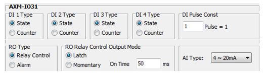
Figure 5: AXM-IO3 Settings
 X
X