Ensure that the baud rate of the device is set to 9600, parity is none1 (or parity none, stop bit 1).
One of the standalone transceivers must be connected to the USB port of a computer in order to configure the transceivers in the network.
Open the AcuMesh software. The following screen will appear.
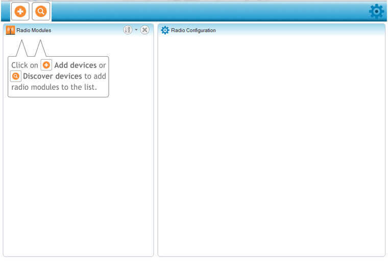
Figure 2: AcuMesh Software
To begin, the software will need to locate the transceiver that is connected to the computer’s USB port. Click on the '+' to discover the Com port that the transceiver is connected to.
Select the Com port and click on 'Finish'.
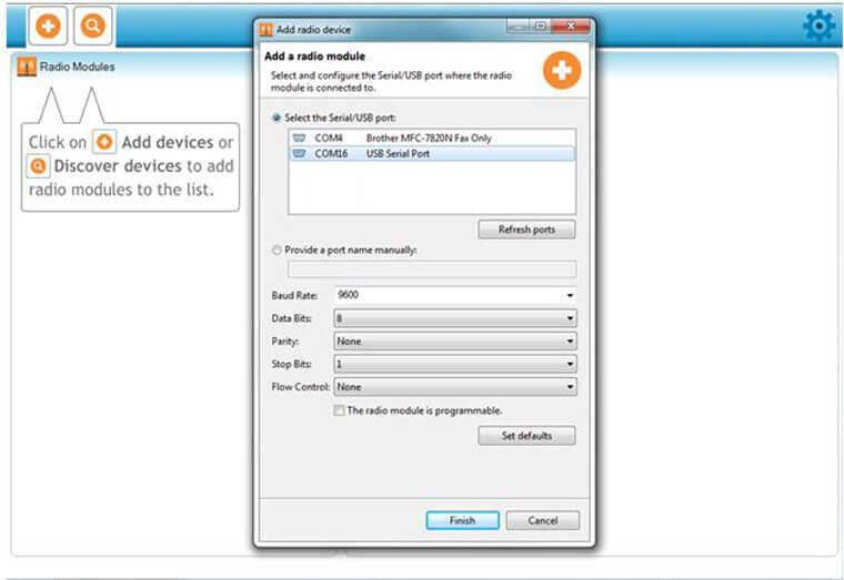
Figure 3: Connecting the Transceiver to AcuMesh Software
Click on the discovered transceiver to view and configure the settings related to this transceiver.
The right side of the window will display the information and settings related to the transceiver under the "Radio Configuration" view.
Note: To configure a remote transceiver in the network, the transceiver needs to be in “remote control mode”
Under the "Stand-alone Transceiver Configuration" section, change the "AP Mode Options" setting from "AT-Communication Mode[0]" to AP1-Remote Control Mode[1]". This will allow you to configure the transceivers that are connected in the network.
 Click this icon to write this setting to the transceiver.
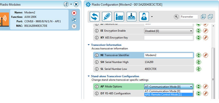
Figure 4: Enable Remote Control
The next step is to enable the transceiver so that it can communicate through the RS-485 port of the device it will be connected to.
Change the "D7 RS485 Configuration" from "CTS flow control [1]" to "RS-485 Enable, High [7]".
 Click this icon to write this setting to the transceiver.
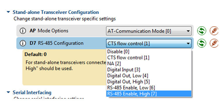
Figure 5: Enabling Communication Through RS485 Port
This step needs to be repeated for all the transceivers connected to a RS485 port within the network.
 To discover other transceivers within the network press this option besides the transceiver that is connected to the computer’s USB port under the ‘Radio Modules’ view. All the remote devices that are in the same network as this transceiver that are found will appear in the pop up box. Press “Add Selected Devices”.
Once added, these remote devices will appear under the local standalone transceiver and will be denoted as remote modules.
Note: By default these remote modules will be identified by their MAC Address.
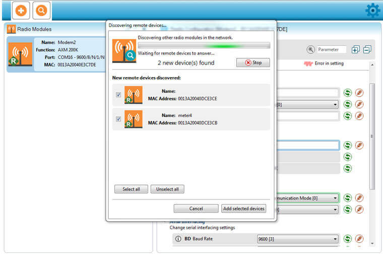
Figure 6: Discover Other Transceivers
To configure the settings for the remote modules, select one remote transceiver at a time and Change the "D7 RS485 Configuration" from "CTS flow control [1]" to "RS-485 Enable, High [7]" which is under the "Stand alone Transceiver Configuration" section.
 Click this icon to write this setting to the transceiver.
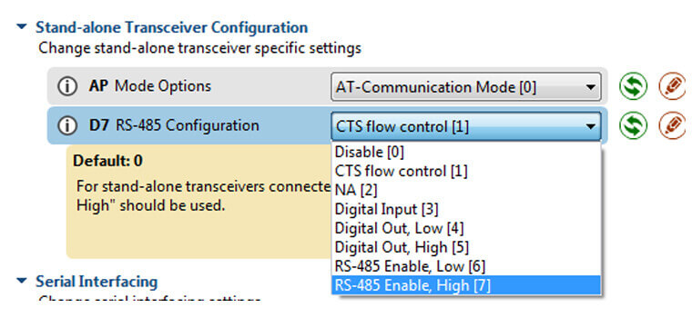
Figure 7: Enabling Communication
Once this setting has been changed on transceivers, click on the master transceiver (the transceiver connected to the USB of the computer) and change back the "AP Mode Options" setting to "AT-Communication Mode[0].
 Click this icon to write this setting to the transceiver.
All the transceivers are now configured to communicate with each other through the RS485 port of the device it is connected to.
 X
X 
 X
X  X
X  X
X